# ESP32快速参考
# ESP32介绍
ESP32是中国乐鑫公司设计生产的一款全球流行的Wifi和蓝牙系统级芯片(SoC)。
# 基本参数
ESP32芯片的数据手册和其他参考资料可以从芯片官网获得:
www.espressif.com (opens new window)。
为了方便起见,下面提供一些基本技术规格:
- 架构:Xtensa双核32位LX6
- CPU频率:最高240MHz
- 可用总内存:528KB(部分保留给系统使用)
- 引导ROM:448KB
- 内部闪存:无
- 外部FlashROM:通过SPI Flash的代码和数据;通常大小4MB
- GPIO:34(GPIO与其他功能复用,包括外部FlashROM,UART等)
- UART:3个RX / TX UART(无硬件握手),一个仅TX的UART
- SPI:4个SPI接口(其中一个用于FlashROM)
- I2C:2个I2C(可在任何引脚上使用bitbang)
- I2S:2
- ADC:最多18个通道的12位SAR ADC
- DAC:2个8位DAC
- RMT:8个通道,可进行精确的脉冲发送/接收
# ESP32开发板
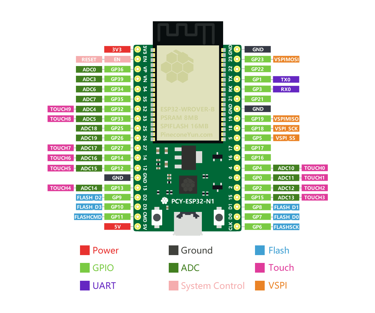
基于ESP32芯片的开发板,市面上非常多,松果云提供的ESP32开发板支持网页版IDE开发。 详细请看 PcyIDE指南
# 通用硬件控制
本ESP32开发板使用MicroPython作为开发语言,使用自身集成的PcyIDE作为开发环境。
# machine模块
更多详细说明请参考machine。
import machine

machine.freq()          # 获取当前CPU的频率
machine.freq(240000000) # 设置CPU的频率为240 MHz
# esp模块
更多详细说明请参考esp。
import esp

esp.osdebug(None)       # 关闭输出调试信息
esp.osdebug(0)          # 重新定向调试信息到UART(0)

# 操作Flash程序存储器的底层方法
esp.flash_size()
esp.flash_user_start()
esp.flash_erase(sector_no)
esp.flash_write(byte_offset, buffer)
esp.flash_read(byte_offset, buffer)
注意
直接擦写Flash可能会导致自带的固件损坏,请慎重使用。
# esp32模块
更多详细说明请参考esp32。
import esp32

esp32.hall_sensor()     # read the internal hall sensor
esp32.raw_temperature() # read the internal temperature of the MCU, in Fahrenheit
esp32.ULP()             # access to the Ultra-Low-Power Co-processor
注意
由于芯片在运行时会变热,因此ESP32中的温度传感器的读数通常会高于环境温度。 从睡眠中醒来后立即读取温度传感器可将这种影响最小化。
# 网络
# network模块
更多详细说明请参考network。
import network

wlan = network.WLAN(network.STA_IF) # create station interface
wlan.active(True)       # activate the interface
wlan.scan()             # scan for access points
wlan.isconnected()      # check if the station is connected to an AP
wlan.connect('essid', 'password') # connect to an AP
wlan.config('mac')      # get the interface's MAC adddress
wlan.ifconfig()         # get the interface's IP/netmask/gw/DNS addresses

ap = network.WLAN(network.AP_IF) # create access-point interface
ap.active(True)         # activate the interface
ap.config(essid='ESP-AP') # set the ESSID of the access point
下面的函数在连接Wi-Fi网络的时候很有用:
def do_connect():
    import network
    wlan = network.WLAN(network.STA_IF)
    wlan.active(True)
    if not wlan.isconnected():
        print('connecting to network...')
        wlan.connect('essid', 'password')
        while not wlan.isconnected():
            pass
    print('network config:', wlan.ifconfig())
一旦网络建立, 你就可以用熟悉的socket来创建和使用TCP/UDP套接字。 并且urequests模块可用于方便的HTTP请求。
# 延时和时间
# time模块
更多详细说明请参考time。
import time

time.sleep(1)           # sleep for 1 second
time.sleep_ms(500)      # sleep for 500 milliseconds
time.sleep_us(10)       # sleep for 10 microseconds
start = time.ticks_ms() # get millisecond counter
delta = time.ticks_diff(time.ticks_ms(), start) # compute time difference
# 定时器
更多详细说明请参考machine.Timer。
支持虚拟的 (基于RTOS) 的定时器。 timer ID 为 -1:
from machine import Timer

tim = Timer(-1)
tim.init(period=5000, mode=Timer.ONE_SHOT, callback=lambda t:print(1))
tim.init(period=2000, mode=Timer.PERIODIC, callback=lambda t:print(2))
period 的单位是毫秒,period为定时时间,每经过这段时间就会执行callback函数。
# 引脚和GPIO
更多详细说明请参考machine.Pin。
from machine import Pin

p4 = Pin(4, Pin.OUT)    # create output pin on GPIO4
p4.value(0)             # set pin to high level
p4.value(1)             # set pin to low level

p5 = Pin(5, Pin.IN)     # create input pin on GPIO2
print(p5.value())       # get value, 0 or 1

p4 = Pin(4, Pin.IN, Pin.PULL_UP) # enable internal pull-up resistor
p5 = Pin(5, Pin.OUT, value=1) # set pin high on creation
可供使用的引脚有: 0, 2, 4, 5, 12, 13, 14, 15, 16, 17, 18, 19, 21, 22, 23, 25, 26, 27, 32, 33, 34, 35, 36,39. 它们是芯片实际GPIO的引脚标号。 注意很多开发板使用他们自己的特殊编号(比如D0, D1, …)
因为MicroPython支持许多的板子和模组,使用物理的引脚编号是因为它们是最通用的编号。 为了对应你的板子的逻辑引脚和物理芯片上的引脚,参考你的板子的文档。
注意
GPIO0 和 GPIO2 是 strapping pin, 它们可能会影响启动. GPIO1 和 GPIO3 是 REPL串口 TX RX 引脚. GPIO6-11 一般连接到 SPI flash. GPIO34-39 只能被设置为输入模式,并且软件没有上拉/下拉功能。
# PWM (脉宽调制)
PWM 可以在所有的输出引脚上使用。 ESP32有8个PWM通道,它们使用同一个频率(范围1~78125HZ)。 占空比在0~1023之间。 更多详细说明请参考machine.PWM。
from machine import Pin, PWM

pwm4 = PWM(Pin(4))      # create PWM object from a pin
pwm4.freq()             # get current frequency
pwm4.freq(1000)         # set frequency
pwm4.duty()             # get current duty cycle
pwm4.duty(200)          # set duty cycle
pwm4.deinit()           # turn off PWM on the pin

pwm5 = PWM(Pin(5), freq=5000, duty=512) # create and configure in one go
注意
GPIO0 和 GPIO2 是 strapping pin, 它们可能会影响启动. GPIO1 和 GPIO3 是 REPL串口 TX RX 引脚. GPIO6-11 一般连接到 SPI flash. GPIO34-39 只能被设置为输入模式,并且软件没有上拉/下拉功能。
# ADC (模数转换)
更多详细说明请参考machine.ADC。
from machine import Pin, ADC

adc = ADC(Pin(35))            # create ADC object on ADC pin
adc.read()                    # read value, 0-4095s
注意
ADC 在引脚 32~39 上可用。 GPIO37-38 一般连接到一个电容,用于 ADC_PRE_AMP。 ADC 引脚的输入电压在0v 到 1.1v之间。
# UART (通用异步收发器)串口
ESP32芯片上,有3个 UART控制器。 更多详细说明请参考machine.UART。
| Pin | rx | tx |
|---|---|---|
| UART0 | 3 | 1 |
| UART1 | 23 | 19 |
| UART2 | 5 | 18 |
注意
UART0 已经被 REPL 使用。
from machine import Pin, UART

uart1 = UART(1, 115200)
uart1.any()
uart1.write('hello world!')
uart1.read(1)
# 软件 SPI 总线
有两个SPI驱动,一个是软件实现的(bit-banging),可以用于任何引脚。 更多详细说明请参考machine.SPI。
from machine import Pin, SPI

# construct an SPI bus on the given pins
# polarity is the idle state of SCK
# phase=0 means sample on the first edge of SCK, phase=1 means the second
spi = SPI(-1, baudrate=100000, polarity=1, phase=0, sck=Pin(0), mosi=Pin(4), miso=Pin(5))

spi.init(baudrate=200000) # set the baudrate

spi.read(10)            # read 10 bytes on MISO
spi.read(10, 0xff)      # read 10 bytes while outputing 0xff on MOSI

buf = bytearray(50)     # create a buffer
spi.readinto(buf)       # read into the given buffer (reads 50 bytes in this case)
spi.readinto(buf, 0xff) # read into the given buffer and output 0xff on MOSI

spi.write(b'12345')     # write 5 bytes on MOSI

buf = bytearray(4)      # create a buffer
spi.write_readinto(b'1234', buf) # write to MOSI and read from MISO into the buffer
spi.write_readinto(buf, buf) # write buf to MOSI and read MISO back into buf
# 硬件 SPI 总线
硬件的 SPI 更快 (高达80Mhz),因为esp32的GPIO Matrix功能,你可以在任意的引脚绑定。
原生SPI引脚:
| SPI | id | clk | mosi | miso |
|---|---|---|---|---|
| HSPI | 1 | 14 | 13 | 12 |
| VSPI | 2 | 18 | 23 | 19 |
原生引号 最大的 SPI 时钟可以到达 80 MHZ. 如果你使用了 gpio matrix 连接到其他的引脚, 最大 spi 时钟是 40 MHz(半双工),26 MHz(全双工) 所以,大多数情况下(当你不需要大于26MHZ的速度), miso你可以使用任意的引脚,mosi, clk & cs使用任意的输入输出引脚。
注意
因为 DMA 冲突,你只能同时使用一个spi总线, 但是一个spi总线可以连接很多设备,使用不同的cs引脚。 他和上面的软件SPI驱动有相同的方法,除了引脚参数和编号:
from machine import Pin, SPI

hspi = SPI(1, sck=Pin(14), mosi=Pin(13), miso=Pin(12), baudrate=80000000)
vspi = SPI(2, sck=Pin(18), mosi=Pin(23), miso=Pin(19), baudrate=80000000)

#or any pin with up 24MHZ

hspi = SPI(1, sck=Pin(5), mosi=Pin(4), miso=Pin(6), baudrate=24000000)
vspi = SPI(2, sck=Pin(12), mosi=Pin(13), miso=Pin(14), baudrate=10000000)
# I2C总线
I2C驱动是软件实现的,并且在所有的引脚上都可以使用。 更多详细说明请参考machine.I2C。
from machine import Pin, I2C

# construct an I2C bus
i2c = I2C(scl=Pin(22), sda=Pin(21), freq=100000)
print(i2c.scan())
i2c.readfrom(0x3a, 4)   # read 4 bytes from slave device with address 0x3a
i2c.writeto(0x3a, '12') # write '12' to slave device with address 0x3a

buf = bytearray(10)     # create a buffer with 10 bytes
i2c.writeto(0x3a, buf)  # write the given buffer to the slave
# 实时时钟 (RTC)
更多详细说明请参考machine.RTC。
from machine import RTC

rtc = RTC()
rtc.datetime((2017, 8, 23, 1, 12, 48, 0, 0)) # set a specific date and time
rtc.datetime() # get date and time
# 看门狗 (WDT)
更多详细说明请参考machine.WDT。
from machine import WDT

# enable the WDT with a timeout of 5s (1s is the minimum)
wdt = WDT(timeout=5000)
wdt.feed()
# 深度睡眠模式
以下代码可用于睡眠,唤醒并检查重置原因:
import machine

# check if the device woke from a deep sleep
if machine.reset_cause() == machine.DEEPSLEEP_RESET:
    print('woke from a deep sleep')

# put the device to sleep for 10 seconds
machine.deepsleep(10000)
TIP
- deepsleep()不带参数的调用,将使设备无限期进入睡眠状态
- 软件重置不会更改重置原因
- 可能有一些泄漏电流流过使能的内部上拉电路。为了进一步降低功耗,可以禁用内部上拉:
p1 = Pin(4, Pin.IN, Pin.PULL_HOLD)
进入深度睡眠状态后,可能需要通过以下方式显式地松开该引脚(例如,如果它是输出引脚):
p1 = Pin(4, Pin.OUT, None)
# OneWire 驱动
OneWire 驱动是软件实现的,并且在所有的引脚上都可以使用:
from machine import Pin
import onewire

ow = onewire.OneWire(Pin(12)) # create a OneWire bus on GPIO12
ow.scan()               # return a list of devices on the bus
ow.reset()              # reset the bus
ow.readbyte()           # read a byte
ow.writebyte(0x12)      # write a byte on the bus
ow.write('123')         # write bytes on the bus
ow.select_rom(b'12345678') # select a specific device by its ROM code
这是一个DS18S20和DS18B20的专门的驱动。
import time, ds18x20
ds = ds18x20.DS18X20(ow)
roms = ds.scan()
ds.convert_temp()
time.sleep_ms(750)
for rom in roms:
	print(ds.read_temp(rom))
请确定一个4.7k的上拉电阻连接在信号线。 注意 convert_temp() 方法一定在你想测量温度的时候调用。
# NeoPixel 驱动
更多详细说明请参考neopixel。
from machine import Pin
from neopixel import NeoPixel

pin = Pin(4, Pin.OUT)   # set GPIO4 to output to drive NeoPixels
np = NeoPixel(pin, 8)   # create NeoPixel driver on GPIO4 for 8 pixels
np[0] = (255, 255, 255) # set the first pixel to white
np.write()              # write data to all pixels
r, g, b = np[0]         # get first pixel colour
NeoPixel还有一个底层的驱动:
import esp
esp.neopixel_write(pin, grb_buf, is800khz)
# TouchPad 驱动
ESP32提供了10个电容触摸引脚。 它们分别是: 0, 2, 4, 12, 13, 14, 15, 27, 32, 33 当用户触摸表面,电容的变化会触发,一个信号的值会返回。 更多详细说明请参考TouchPad。
from machine import Pin, TouchPad

tc = TouchPad(Pin(4))   # create TouchPad driver on GPIO4
tc.read()               # when touch the pad, the value will low around 80;
                        # if float ,the value is around 1000
# DHT 驱动
DHT驱动是软件实现的,并且工作在所有的引脚。
import dht
import machine

d = dht.DHT11(machine.Pin(4)) d.measure() d.temperature() # eg. 23 (°C) d.humidity() # eg. 41 (% RH)
d = dht.DHT22(machine.Pin(4)) d.measure() d.temperature() # eg. 23.6 (°C) d.humidity() # eg. 41.3 (% RH)